Circular Interpolator
tim.circular.line.maxpat
tim.circular.line.random.maxpat
README
LICENSE
Circular interpolation is not necessarily trivial. Whenever you want to interpolate around a circle, you do not want to do it linearly. If, say, you start from a 10˚ position and want to interpolate to 350˚, you do not necessarily want to interpolate from 10˚ to 350˚ directly, but rather from 10˚ to -10˚, which warps around as the mathematical modulo of -10 % 360 = 350. Say, for example, I have several steps to interpolate along: 10˚, 140˚, 270˚, 400˚(=40˚). In the first two interpolations the direction is clear, as we interpolate upward from 10˚ to 140˚ and again from 140˚ to 270˚. But, when we hit the last interpolation, we do not want to interpolate downward from 270˚ to 40˚ (almost once around the circle), but we'd rather want to continue interpolating upward to 360˚, jump to 0˚ and continue interpolating upward until we reach 40˚.
Quick side note before we fully dive into this: for the remainder of this text – and because we're talking about Max/MSP, a music programming language for, among other things, musical interfaces – I am considering that moving around a circle is done in the opposite direction of the usual mathematical sense. This means that values increase when going clockwise around the circle! Sorry if this confuses anyone reading on, but it's how it going to be from here on, ok?
my story
I have often encountered this problem in Max/MSP while programming spherical audio applications or compositions and stupidly re-invented the wheel many times until I finally sat down to program my own little helper sub-patch tool. The problem is that regular interpolation is linear, of course. So, in order to interpolate to a new angle, we need to somehow correctly decide if we want to interpolate upwards or downwards. This is equivalent to moving clockwise or counter-clockwise along the circle. Additionally, we have to consider that the final result should stay within the [0˚,360˚[ interval by using the mathematical modulo. Although this is not strictly necessary, keeping your resulting values inside this range helps you determine the circular distance for any two values more accurately.

Take the image above, for example. This is one intuitive idea I first had, thinking it could have been an elegant solution: we construct the intersecting vector from the old position to the new position on the circle and simply interpolate along this vector. This would imply we would always interpolate through the center of the circle, hence taking the smallest possible path to each new interpolation point. To receive an interpolation along the circle perimeter, we simply create a projection from the circle center, through the interpolation point along the vector and out to the perimeter of the circle. Unfortunately, this method has one significant flaw, in that the linear movement along the vector results in a non-linear change in angle. This means, that the projection also is not linear in relation to the distance traversed along the circle perimeter. The result is an increase in speed in circular interpolation as we get closer to the center when traversing the vector – or, as the distance between the interpolation point along the vector and projection point increases.
I have also tackled this problem in previous solutions with convoluted if-statements, checking if the smaller distance to the current value is either above or below it (i.e. clockwise or counter-clockwise of the circle). Patched connections would go everywhere and the sub-patches would be a mess after I got it working correctly. Eventually I went back to the drawing board and decided to finally build a good solution that I would keep handy as a sub-patcher in my file path.
tim.circular.line
To publish this code, I have chosen to clean-up and properly document my most elegant approach. It consists of shifting the value-to-interpolate-to (the new value) by the amount of the value-to-interpolate-from (the previous value). This centers the new value in relation to the old value. If we now shift the result by 180˚ and take it's modulo of 360˚, we have effectively centered the new value around the old one. Hence, simply interpolating to this new resulting value already takes the decision to either go left or right of the circle for us correctly! What is left is to shift the result back to its original range, meaning shift it back by 180˚ and by the old value.
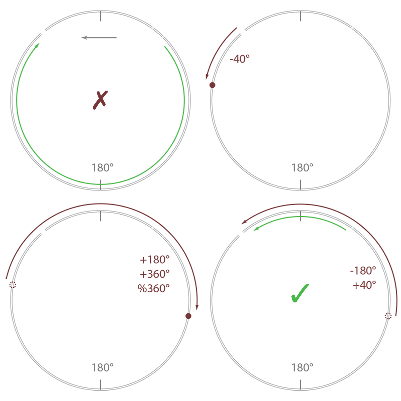
Let's look at an example: in the above image (section a) you can see that we want to interpolate from 40˚ to 320˚. If we were to interpolate using these values directly, we would take the long way around, past 180˚ at the bottom, which is not what is generally desired. By applying the shift against the value-to-interpolate-from (40˚, in section b), shift if further by 180˚ and take the mathematical modulo (section c), we push the value-to-interpolate-to to be centered around the value-to-interpolate-from. What remains is to shift the value-to-interpolate-to back to it's original position, which now became the negative equivalent of the original value-to-interpolate-from (section d).
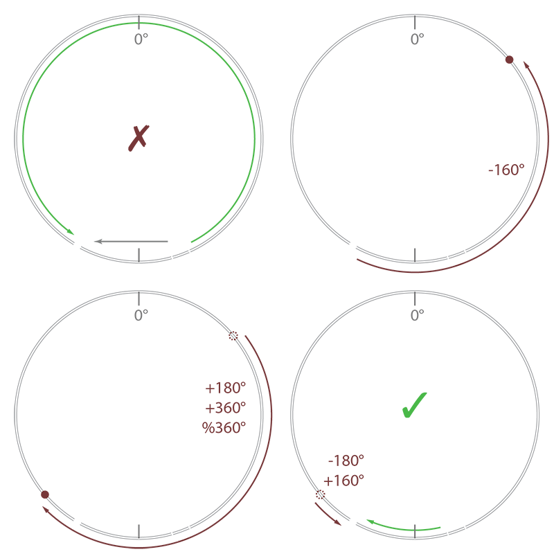
Now, you might look at this example and think we just took a complicated route to arrive at value that is within ]-180˚,180˚]. But this is not entirely true. Look at the second example above. This time we want to interpolate from 160˚ to -150˚. Although these values are within the ]180˚,180˚] range, an interpolation using these values would still result in the undesired long way around the circle, this time past 0˚. But if we follow the same steps (move against original value, shift by 180˚ and take mathematical modulo, then shift back) it will result in a value larger than 180˚, but closer to the value-to-interpolate-from, compared to it's equivalent counterpart. The result is the correct, desired short path, past the 180˚ mark.
Note that the resulting value-to-interpolate-to can become either smaller 0˚ or greater 360˚, but because we take the modulo of the final interpolation, the actual interpolation will be within the desired [0,360[ range. Another note to be made here, is that one should take care to use the mathematical modulo, since many programming languages maintain a negative result for negative dividends. This does not work for our purpose here and can be avoided in general by adding an additional divisor amount and taking a second identical modulo: ((a%n)+n)%n
Here is a screen shot of the resulting patch:

One nice little feature the circular interpolator has is that the user may choose what to do in ill-defined moments. A circular interpolation is somewhat ill-defined if the new value that one wants to interpolate to lies exactly 180˚ apart from the old one. Technically, both clockwise and counter-clockwise movements are valid. Yet, we have to choose one.
Luckily for us, the formulas used here automatically make the interpolation go counter-clockwise. Meaning, from a mathematical standpoint, this problem is quite well defined. The reason for this is simple: because of how the modulo works when hitting the extreme in a scenario where n mod n gives us zero. This means, that when viewed on a number line, the interpolation will always go down, meaning counter-clockwise. But, luckily for us, we can trick our formulas to go the opposite direction by being just slightly underneath our divisor n. By subtracting a minimal delta we prevent this modulo to wrap around and make the interpolation go upward on our number line, i.e. clockwise around the circle. The assumption we're making here is that this delta should be small enough that the small region between n and n+delta is most likely never going to be hit, causing the rotation to go in the wrong direction! Furthermore, you could also say that delta should be small enough so that should this case actually happen, it can be seen as irrelevant, even if it is technically wrong, because it's so close to our divisor n anyway, so, not a big deal, really.
tim.circular.line.random
A second sub-patch included in this package is a helpful tool that constantly walks along the circle in a random, brownian noise fashion. Its parameters are merely a minimum and maximum ramp time, between which a random time is chosen for each new ramped value. Using the circular line tool described above one could possibly program his or her own random movement patch.
But, there are two reasons why my random circle walker does not use the aforementioned circular interpolation. First, I started programming the random circle movement patch before doing the general purpose circular interpolation. Secondly, this patch makes use of some generalizations about the random movement that simplify it, even if just a little.
For one, we know that we will maximally walk +/- 180˚ away from our current position. So, we can directly construct a new position to interpolate to simply by choosing a random value 180˚ around the old one. Furthermore, this patch can be nicely activated and stopped with a simple toggle object, hence I hope usage is quite simple and intuitive. Doing something like this yourself is perhaps not that easy. I want people to have a handy random circular walk sub-patch at hand, ready to go and easy to use. It's done, so if you need it, use it!

additional information
There are, most likely, a few questions I can can clear up right away. First, how would I extend this to 3D? In both the circular interpolation and random circular walk, you can load two instances for both horizontal (azimuth) and vertical (elevation). When using the circular interpolation you should take care, though, to never go beyond +/-90˚ (or 0˚ to 180˚ in mathematical terms). If you need to include going beyond these values to warp around the top also, be sure to flip the sign of your azimuth value when moving beyond 90˚ elevation or below -90˚ elevation. Perhaps I will build and include nifty tools to directly interpolate and walk along a sphere in 3D myself, so that these hacks will not be necessary anymore.
Secondly, one might think that the maximum they can traverse around a circle is 180˚ at any given value. While this is true, this is also conform to the definition of this module. If you absolutely need to move more than 180˚ in any given direction, halve the interpolation time and insert an intermediary interpolation step. So instead of going from 0˚ to 270˚ in 1000ms, you can choose to go from 0˚ to 135˚ in 500ms and from 135˚ to 270˚ in 500ms. When using the random circular walk, you can basically simply scale the values to your liking, as they are random anyway. So, if you want absolutely need to move a maximum of 360˚ degrees around a circle in one constant, random direction, simply multiply the output by 2.
Finally, you don't necessarily need to only use this in degrees, of course. The easiest way to scale this to any value is to divide the output by 360 and multiply it by anything you need. The reason I programmed these tools to work in degrees is that it will be easiest for anyone to hopefully understand what it does exactly in the fastest way possible – and, because this is what I needed these tools for myself. Using radians or a normalized range does not necessarily correlate with the average world. Sure radians would be more mathematical, a normalized range perhaps even practical in some cases, but Max/MSP is not primarily made for mathematicians or engineers, so I hope this way it will be used by as many people as there might be out there who can make use of this...
conclusion
They might be small tools, but I do think they are very handy if you're doing anything circular with Max/MSP or perhaps even Jitter. If you do use them, it would be great to give me a shout and I hope it goes without saying that one should give credit where credit is due. Please also do contact me with any bug reports or suggestions you might have. Also, if you do any updates and think they should be included in this package, don't hesitate to get in contact with me.